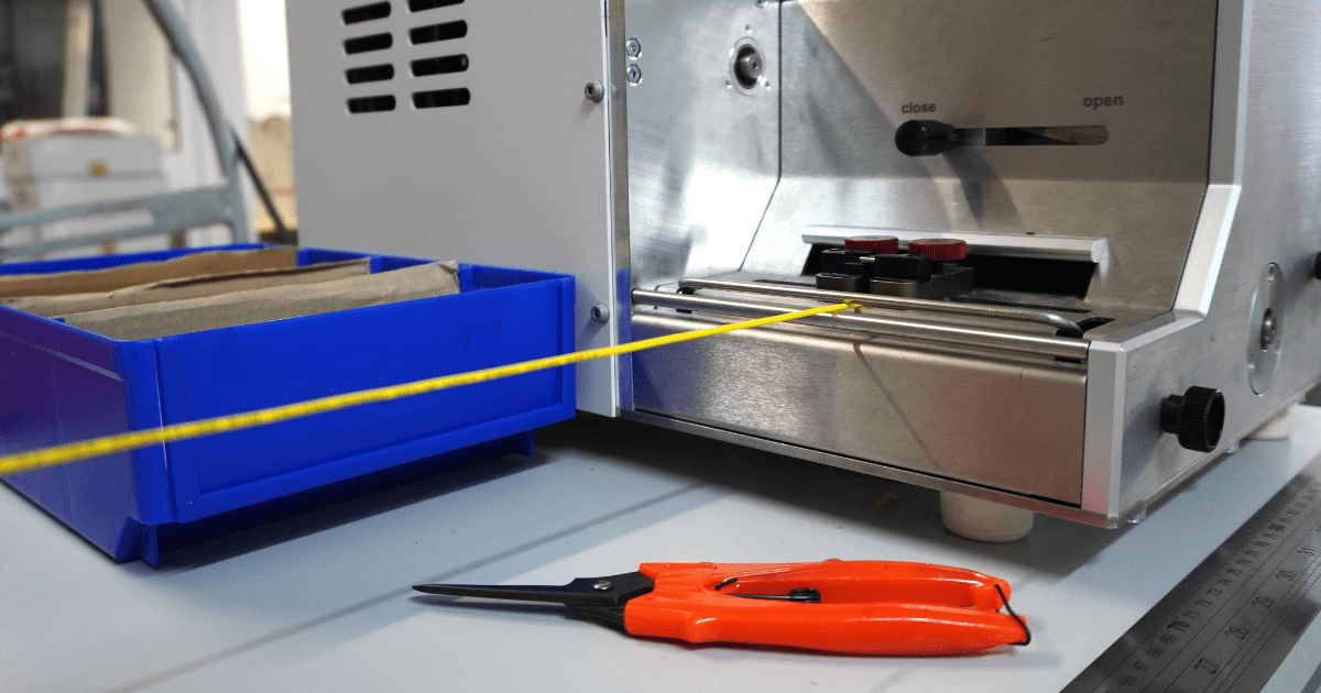
Once the fiber is cut, the cable moves to a new step of the assembly line, the preparation of the fiber for connectorization.
As the phase that comes before, preparing the fiber for connectorization is a part of the manufacturing process, that has some specifications to it.
Boots & Crimping Rings
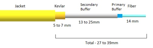
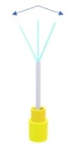
The cable gets to this point of production with the constitution of the figure below:
-min.png?width=435&height=222&name=Blog%20Post%20(10)-min.png)
The first step is to put the appropriate boots and crimping rings for the connector type of polishing we are going to do.
Blue for PC polishing, Green for APC if it is single mode and Beige for OM 1 and 2, Aqua for OM3, Violet for OM4 and Lime for OM5, if it is multi-mode.
Both boots and crimping rings depend on the connector type and manufacturer, so we should not mix components from different manufacturers.
Fiber Stripping
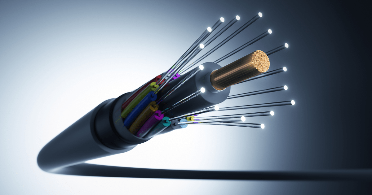
Below is a diagram of a typical fiber optic patch cord cable. Other cables may have more layers or special shielding, but the process is valid for all of them.
In all of them extreme care is required. If in the stripping process, we create a small fissure we will have the same behavior as when we scratch glass to break it.
That crack, as soon as the fiber creates a curve at that point, even if slight, or thermal variations, will expand or even break the fiber. These cracks initially may not be detected in testing, but they will break the fiber when they are placed in ODF and wire passes.
A rule of thumb is that when preparing cables with multiple protective layers, each layer should be stripped individually and with care not to damage the next layer.
- Removing the Jacket
The first layer to remove is the Jacket, which in patch cords is usually 2 to 3mm in diameter. For this isolation we should use fiber stripping pliers on the appropriate hole.
After removing the Jacket check the aramid yarns for damage. Even a small number of damaged fibers can have a big impact on the pull strength of the final product.
The stripping pliers must make a clean cut, the plastic must not be stretched or become jagged.
- Removing the Aramid Yarn
Once the Jacket is removed, we move on to the strength element, Aramid Yarn or Kevlar.
This Aramid Yarn will be the support of the patch cord when it is pulled, it is the one that will absorb the force deflecting it away from the fiber. So, it is very important that it is in the right dimension.
To cut this layer we must use special Kevlar scissors.
- Removing the Secondary & Primary Buffer
The third layer to be removed is the Secondary Buffer. It is usually soft plastic and is 0.9mm in diameter.
There are two tools for this process: Hand pliers in the appropriate hole or heated pliers that will "soften" the plastic before cutting. The blades of the pliers must always be clean and sharp.
The plastic should have a clean circular cut and should not be dragged or jagged. The pliers should be perpendicular to the fiber, not angled or placed sideways.
When removing the Secondary Buffer, ensure that the next layer, the Primary Buffer, has not been touched.
The Primary Buffer is 0.25mm in diameter and can be removed using hand pliers. In some cables, this jacket comes out together with the Secondary Buffer.
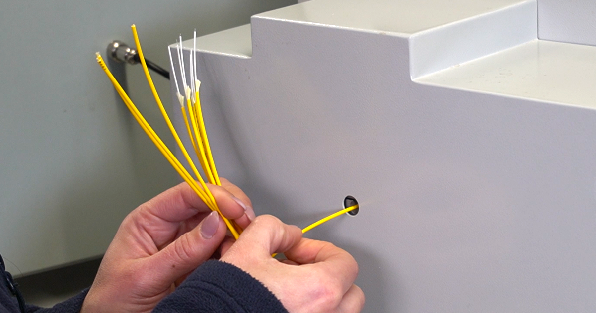
- Verifying the Fiber
After all the layers are stripped to the right extent, we will make sure that the fiber has not been damaged.
To do this we can tilt the fiber about 45° to each side. If somehow the fiber is damaged, it will break at this step.
The entire stripping process can also be done automatically with specific machines. One for Jacket and Kevlar, and another for Primary and Secondary Buffer.
Whether manual or automatic, it is extremely important to keep the blades sharp. In all these isolations the cut must be clean, without leaving burrs or stretching the plastic.
In each new production, the thickness of the various cable isolations must be checked and the necessary adjustments to the tools, whether manual or automatic, must be made.
Another care to be taken is to verify that the measures of the various sheaths are those specified for each type of connector and for each manufacturer. As they don't all have the same structure, the measures of each protection layer that remains after the stripping are different. This has a big impact on the reliability and performance of patch cords.