There are many types of fiber optic cables, so the fiber optic cable manufacturing process will differ mainly in the properties used on the various components of the cable, depending on which type of cable it is.
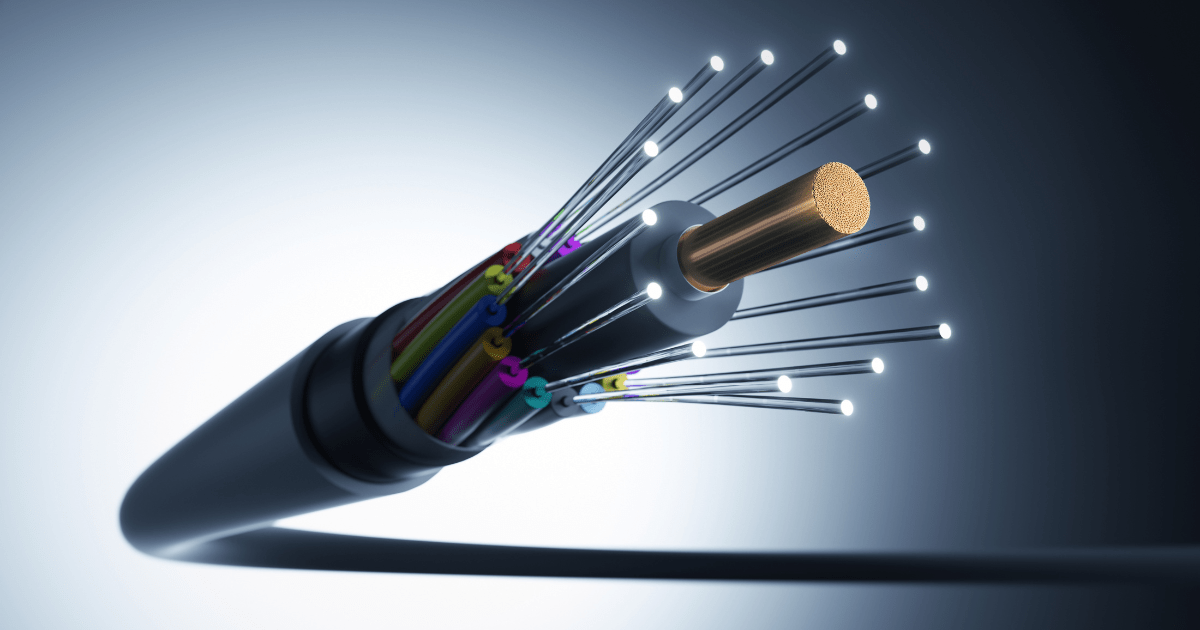
This includes all the fiber optic cable construction components: the core, cladding, coating, buffer, fiber count, cable arrangement, subunits, filling, strength member, and outer jacket. Each of these components has its own characteristics, which leads to an endless variety of cables for each different application.
Image retrieved from Blackbox
Introduction to Fiber Optic Cable Manufacturing Process
Fiber optic cables are a type of cable that can be made up of pure silica, doped silica, glass composite or plastics. Fibers made from pure or doped silica have the best characteristics for telecommunications. Glass composite or plastic fibers have high attenuation and low bandwidth, and are used in short distance, low transmission rate, and lighting systems.
Independently of what material they’re made up from, these cables transmit data over long distances using light signals. They offer several advantages over traditional copper cables, including higher bandwidth, faster speeds, and greater reliability.
The manufacturing process of fiber optic cables involves several key steps:
1. Preform Production:
Usually, we start with a silica tube, made from the raw material (silica) and already with the physical characteristics of the optical fiber to be produced (density). This tube will give origin to the Cladding.
The core of this silica tube will be filled with gases that, when heated, solidify and form the core. After filling the core, the silica tube will originate the glass preform, which is the silica tube with the interior already processed.
There are 4 manufacturing processes for the glass preform:
- MCDV - Modified Chemical Vapour Deposition;
- PVDC - Plasma Chemical Vapour Deposition;
- OVD - Outside Vapour Deposition;
- VAD - Vapour axial deposition.
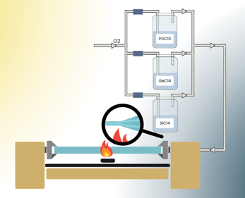
MCDV is the most common, so we will only talk about this one.
|
Inside the silica tube, chloride gases (SiCI4, GeCIe and POCI3) will be injected in controlled concentrations for the final objective. These gases will form the fiber core. The tube is rotated on its axis and heated to 1500 degrees. As the gases are injected, they form deposits on the inner walls of the tube. The amount and density of injection of these gases depends on the type of fiber being built. |
|
After all the layers of gases have deposited on the inside of the tube, the tube is closed, creating the glass preform.
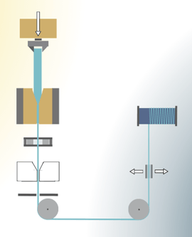
2. Drawing:After testing, the glass preform goes to the draw tower. In this process, the glass preform is placed in a vertical tower and fed into an induction graphite furnace that is heated to approximately 2000 degrees. At this temperature the glass becomes malleable enough that when the Glass Preform is pushed through the furnace the fiber flows through the tower, a diameter gauge controls this process. |
|
3. Coating:
After this process the optical fiber receives its first insulation, Coating.
This Coating can be of various materials depending on the cable application:
- Acrylate Fiber Coating: used in standard telecom fiber in a double layer of Acrylate (softer inner coating and hard outer layer)
- High Temperature Acrylate: Used for its resistance to vapors and to the gel used in the cable. Typically used in harsh environments, industrial sensing and military and aerospace applications
- Fluoracrylate: Ideal for medical applications. Adheres to the surface of the silica covering small flaws and "repairing" these flaws, resulting in improved tensile strength of the fiber and delayed static fatigue.
- Silicone coating: Resistant to water vapor and a range of chemicals, the silicone is soft and requires buffering for protection, usually with thermoplastics like ETFE, PFA or PEEK.
Other possible materials in Coating: Acrylate Coating, Polyimide, Carbon, Polyetheretheerketone (PEEK), Polybutylene terephthalate (PBT), Polypropylene (PP), Polyethylene (PE), LSZH Low Smoke Zero Halogen (PE-PP), Polyvinylchloride (PVC), Polyvinylidene Fluoride (PVDF), Polyurethane (TPU), Halogen free Flame-retardant Polyurethane (HFFR), Hytrel (TPE), Ethylene tetrafluoroethylene (ETFE), Perfluoroalkoxy Teflon (PFA).
4. Cabling:
The number of fibers in a cable is another aspect that influences cable construction. There’s two ways the fibers can be inside the cable:
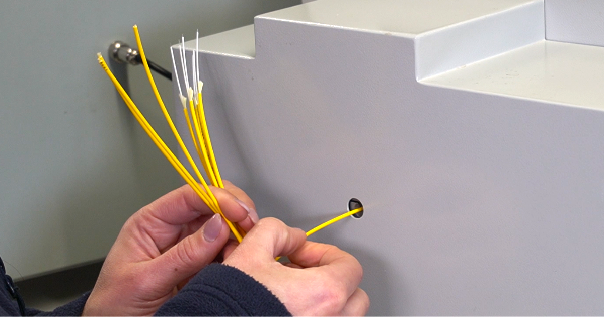
- Tight Buffer: Each fiber has its own insulation "Tight Buffer", which is a protective layer fitted to the fiber, which makes the fiber more resistant to bending and easier to handle. This buffer is usually 0.9mm or 2mm outer diameter and makes it possible to terminate connectors directly on these fibers. Usually used in indoor cables.
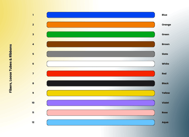
- Loose Tube: A bundle of fibers, usually 12, are placed in a tube that allows for a large number of fibers in a small diameter cable. This loose tube may or may not have a moisture-protective gel. This type of cable is used in outdoor installations, the fibers cannot be terminated directly, but the cable has a much higher resistance to impact and environmental elements.
Whether in tight buffer or loose tube, to build the cable we have to group the fibers.
|
There are 12 standard colors that identify the fibers within the cable. If the cable has more than 12 fibers we need to make subunits to keep all the identified fibers. With the fibers grouped and identified, the next step is to choose the use of the cable: Indoor or Outdoor. |
|
With the cables for indoor use, the jacket is designed to cause the least damage to people in case of fire. They produce little smoke, and are free of materials that produce toxic gases when burning (fluorine, chlorine, bromine and iodine). Thus, the indoor cable is LSZH (Low Smoke Zero Halogen) rated.
In contrast to Indoors, outdoor cables are produced with other concerns: exposure resistance to the environment, humidity, temperature changes, impacts, and UV rays from direct exposure to the sun, animals, etc. Outdoor cables need tensile strength to be pulled over long distances, high resistance to stretch in the case of self-supported cables, high resistance to rodents and other animals in ducted or buried cables, and several other characteristics depending on the installation site.
5. Testing and Inspection:
After the glass preform goes through the draw tower and becomes optical fiber, it is subjected to a series of mechanical, optical and geometrical tests.
The first test is the tensile strength. In this, the fiber must withstand at least 7000kg/cm². After passing this test, the fiber is placed on reels.
Once on the reels, the fiber is subjected to a series of optical tests such as attenuation (power meter) and attenuation uniformity along the fiber (OTDR). The multimode fiber is also tested in bandwidth and numerical aperture (NA) that controls the number of modes that the fiber admits.
Geometric tests include core, clad, and coating diameters, non-circularity, and core/clad offset.
Overall, the fiber optic cable manufacturing process is complex and requires specialized equipment and expertise. However, the resulting cables offer several advantages over traditional copper cables, making them an important technology for modern communication networks.
Applications of Fiber Optic Cables
Fiber optic communication consists of transmitting information from sender to receiver using pulses of infrared light. Whether over long or short distances, fiber optic communication allows the transmission of any type of information that can be converted into pulses of light. Video, voice, data, telemetry (and so on), signals are generated in the equipment as electrical signals. These signals pass through a transmission circuit, a light source, through the fiber to a photodetector, and to the receiver circuit.
The most common light sources are Light Emitting Diodes or Laser's (light amplification by stimulated emission of radiation). The most common photodetectors are PN Junction diodes and Avalanche Diodes.
Because the transmission is in pulses of light, without mass or matter, the communication is immune to electromagnetic interference, providing reliable, high-speed, low-cost, and very low power communication. This makes this form of transmission ideal for many applications:
- Voice, video, data (intranet and ethernet),
- Automotive Industry: The interior of vehicles is illuminated by fiber optics. It requires little space, can be placed anywhere in the vehicle, consume little power, have longer life span, etc. It is also used in various equipment in the vehicle.
- Factory Automation: In factory environments, fiber optics is an excellent means of communication between machines and controllers or between machines themselves as it:
- Enables future upgrades;
- Is immune to EMI (Electromagnetic Interferences);
- Is virtually immune to high temperatures or frequent temperature variations;
- Allows greater distances than copper.
- Robotic Industry: The fiber allows for long-lasting torsion, flexibility, strength and bend radius ideal for use in Robotics.
- Renewable Energy:
- Windpower controls, Solar power control - In this type of installation there are often constraints such as electromagnetic noise, large and frequent temperature variations, vibrations, exposure to chemicals (oils), and the need for rapid repair or replacement of cables or make rapid changes to the existing layout.
- Smart Cities.
- Urban mobility management.
- Efficient public lighting.
- Fiber sensing disaster prevention - Measurement for energy management and distribution, measurement of energy consumption, water leaks monitoring.
- Medical Equipment: Fiber is used in various medical diagnostic equipment like endoscopes, otoscopes, ophthalmoscopes. It is used in these and other equipment because they have no, or virtually no, side effects or harmful consequences, are flexible, and emit no radiation whatsoever. They are also used in applications in the microbiology and biomedical sector.
Quality control of the fiber optic manufacturing process starts with the preform raw material and the application of the core gases. The absence of impurities in these two fiber components is of utmost importance. Various diameter sensors control the entire manufacturing process. From core diameter, clad diameter, and coating diameter.
New manufacturing methods are being developed. Tooling is renewed on average every 18 months to keep up with this constant evolution. In the present, the preform is heated with a high-energy laser and can produce 10 to 20 meters of fiber per second and 2 to 25 kilometers with each Glass preform.
Besides that, the core materials are evolving too. The current fibers have an attenuation per km of 0.2dB. Several other materials are being developed for the core and the most promising one, Zirconium Fluoride (ZrF 4) in about 50% of the core, promises attenuations in the order of 0.005 to 0.008dB per KM.